Computation domain
Create geometry
For this tutorial, one can create an idealized geometry of the Gironde (France) using Gmsh.
Create points
A point is identified by a tag, and defined by a list of four numbers : three coordinates (X, Y, Z) and the target mesh size (lc) close to the point. We will first define the points in our domain, and then the target mesh size in the .geo Gmsh script.
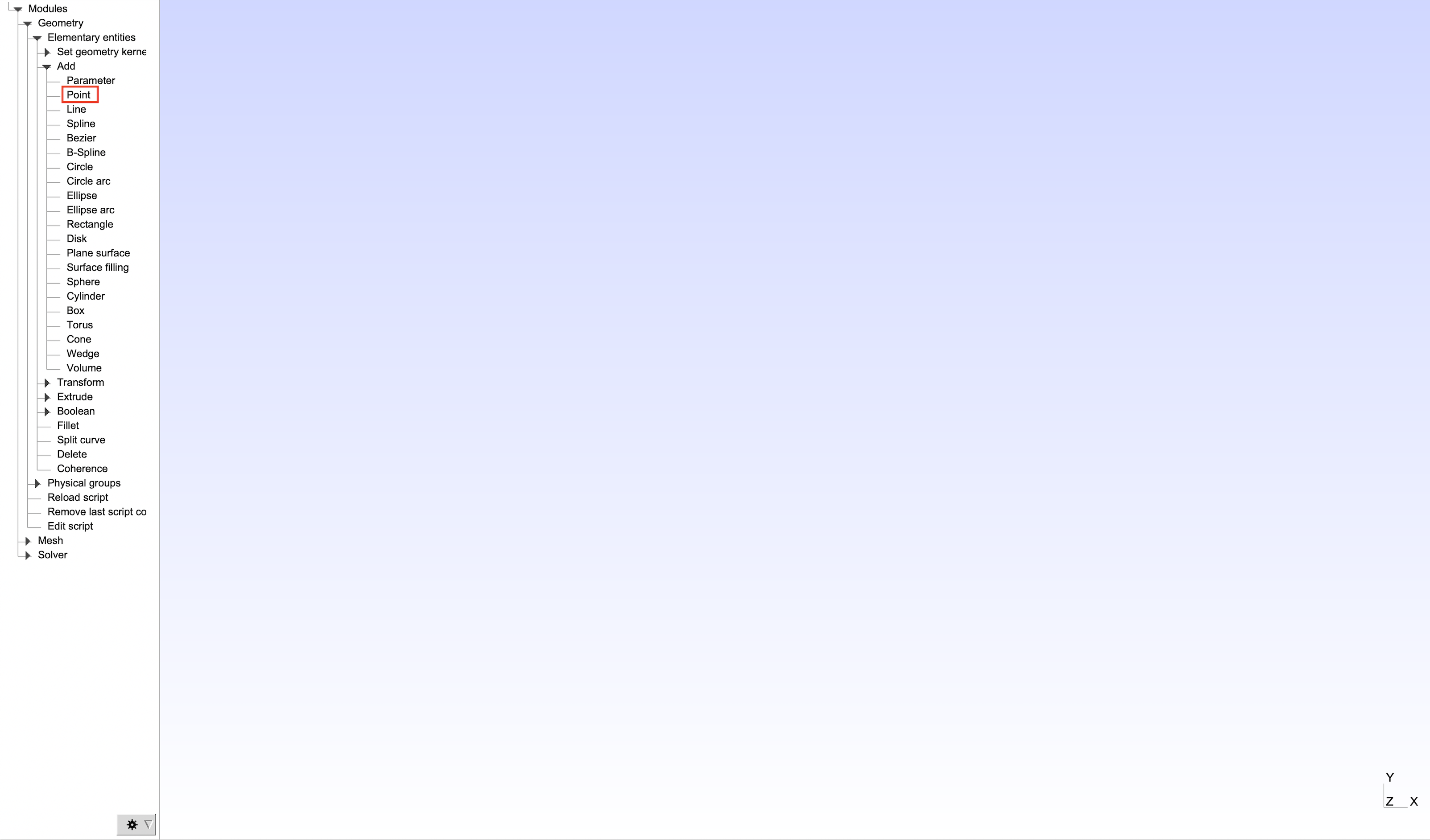
One can create all the geometry points by clicking on Modules > Geometry > Elementary entities > Add > Point.
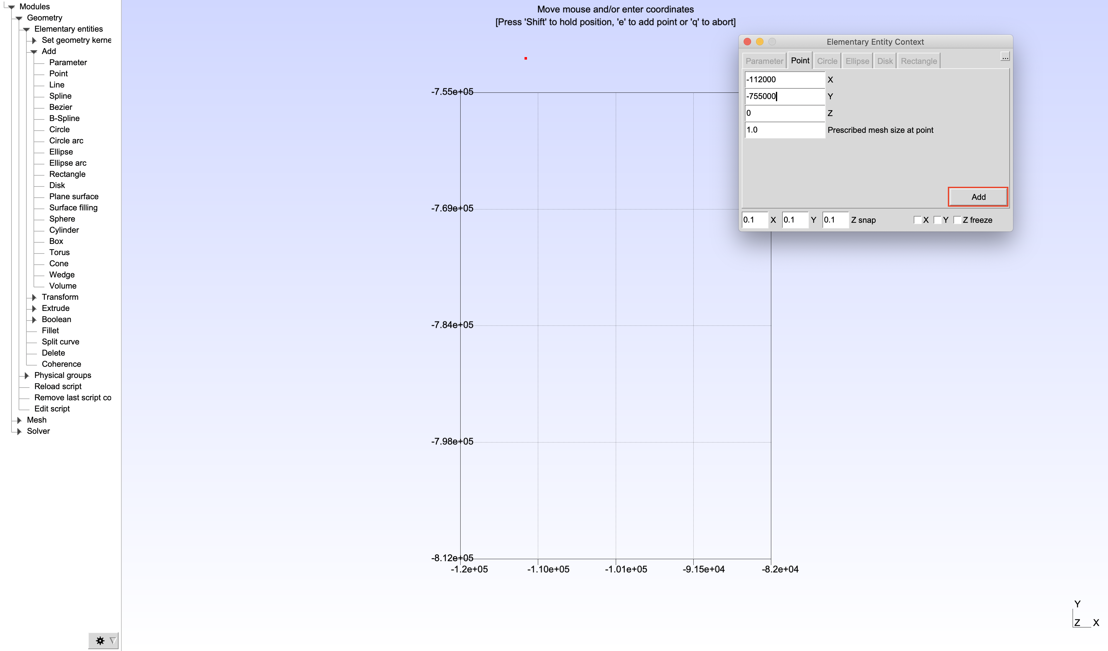
Once the Elementary Entities Context window is open, enter the coordinates of the first point : (-112000, -755000, 0.0), and click on Add.
Create all the other points by using the same methodology :
- Point 2 :
(-92000.0, -770000, 0) - Point 3 :
(-82000.0, -810000, 0) - Point 4 :
(-87000.0, -81200, 0) - Point 5 :
(-98724.3, -779176, 0) - Point 6 :
(-120000, -767000, 0)
Quit the dialog and press 'q' when all the points are created.
Once the points are created, we can define the target mesh size in the .geoscript. Here, we will establish that lc = 600. Defining a global target mesh size enables one to modify it easily.

lc = 600; lc2 = lc/2; lc3 = lc2/2.5;
//+ Points
Point(1) = {-112000, -755000, 0, lc};
Point(2) = {-92000.0, -770000, 0, lc2};
Point(3) = {-82000.0, -810000, 0, lc3};
Point(4) = {-87000.0, -812000, 0, lc3};
Point(5) = {-98724.3, -779176, 0, lc2};
Point(6) = {-120000, -767000, 0, lc};
Create domain edges and surface
When all the points are created, one needs to create the edges to define the boundaries of the domain. Here, only splines will be generated. First, one has to click on Modules > Geometry > Elementary entities > Add > Spline.
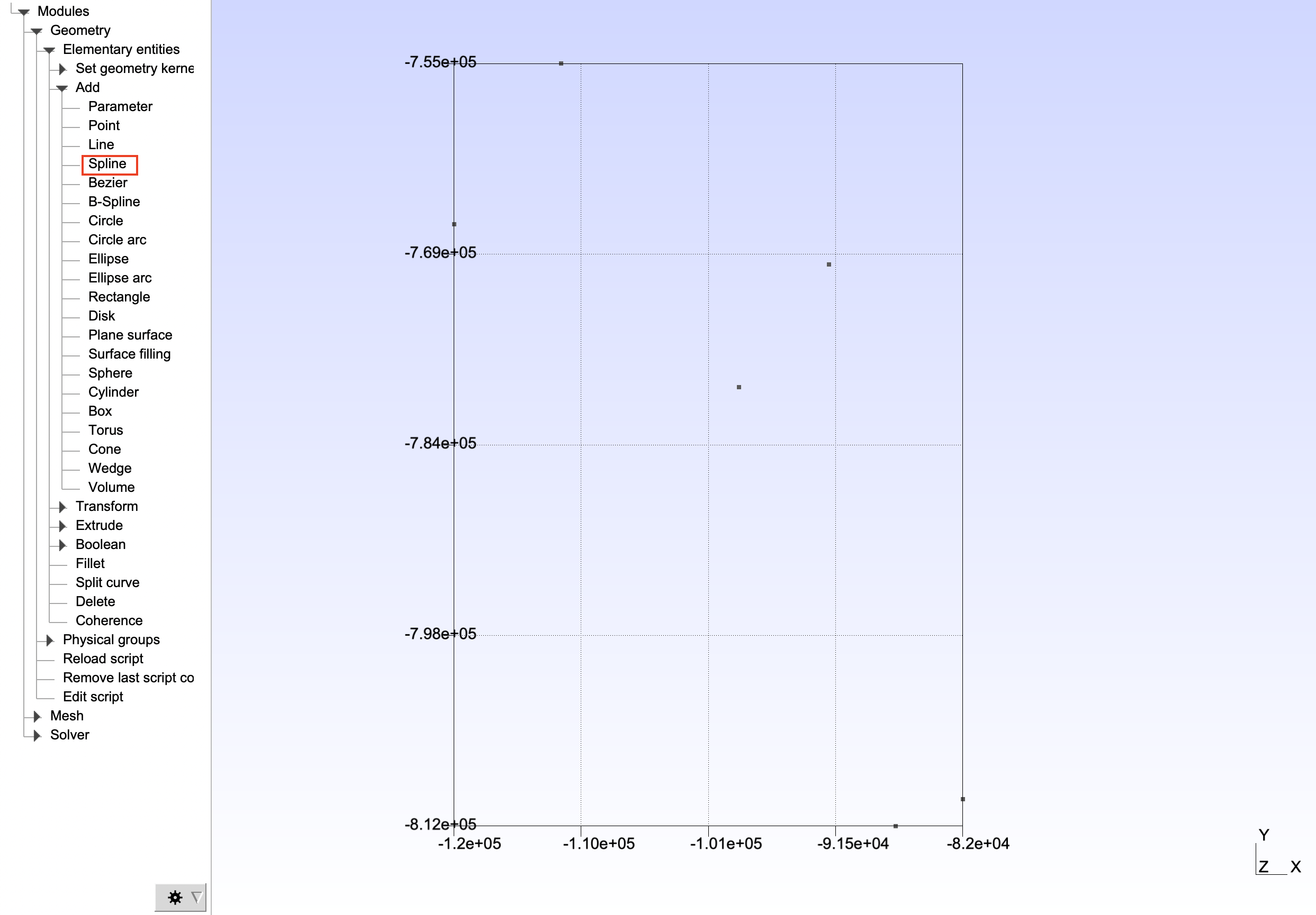
A spline is defined by three control points. Select all three of the following point to create the first spline :
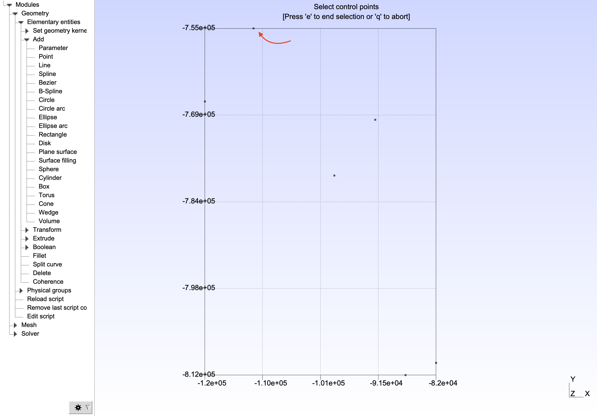
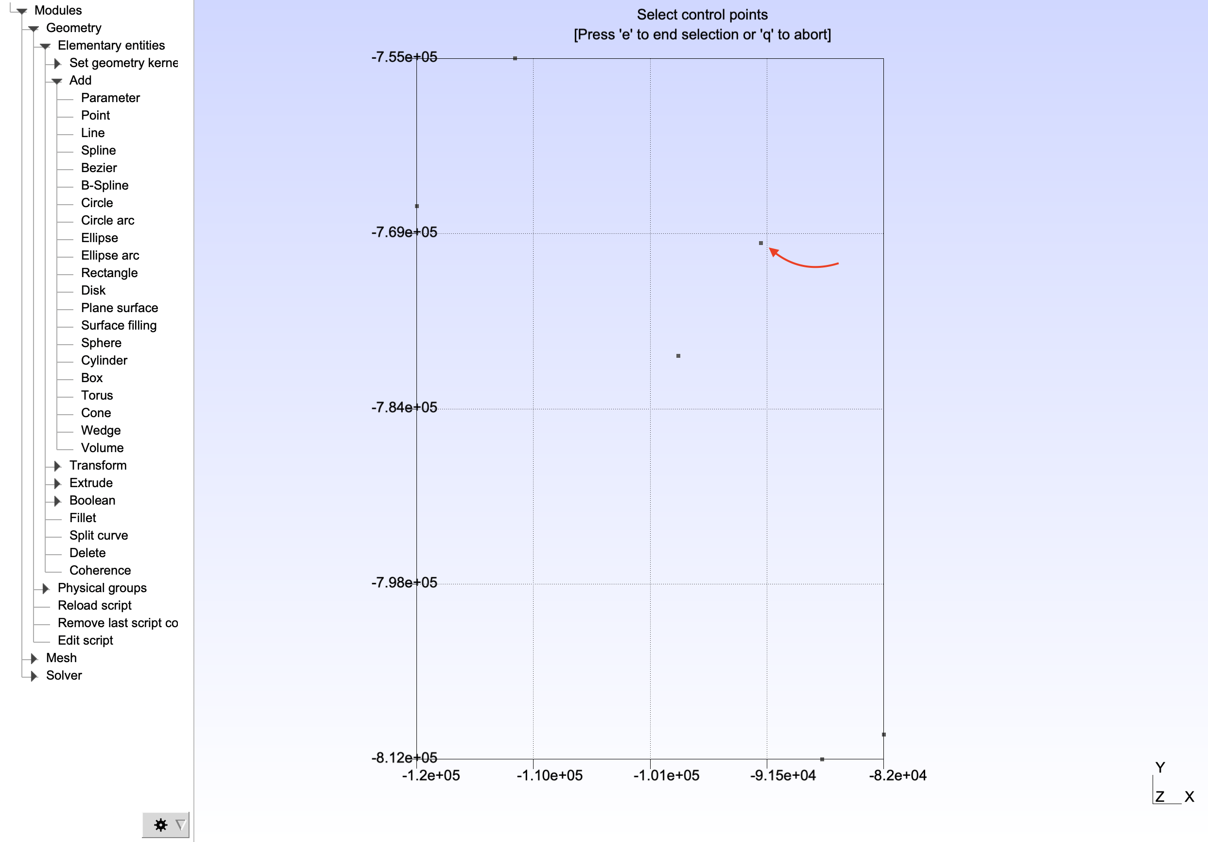
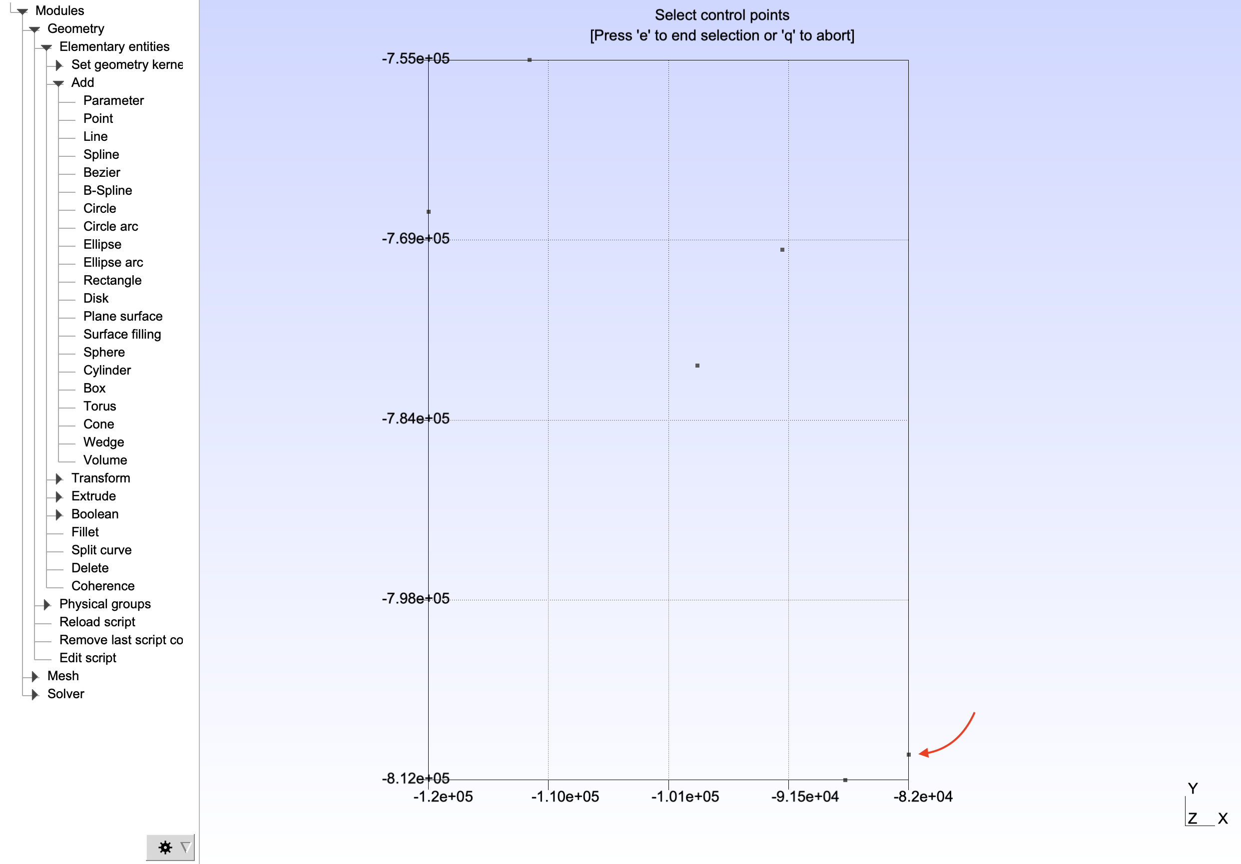
When all the points are selected, press 'e'. Repeat the operation for the three other splines defined by the following points :
- Spline 2 :
(3, 4) - Spline 3 :
(4, 5, 6) - Spline 4 :
(6, 1)
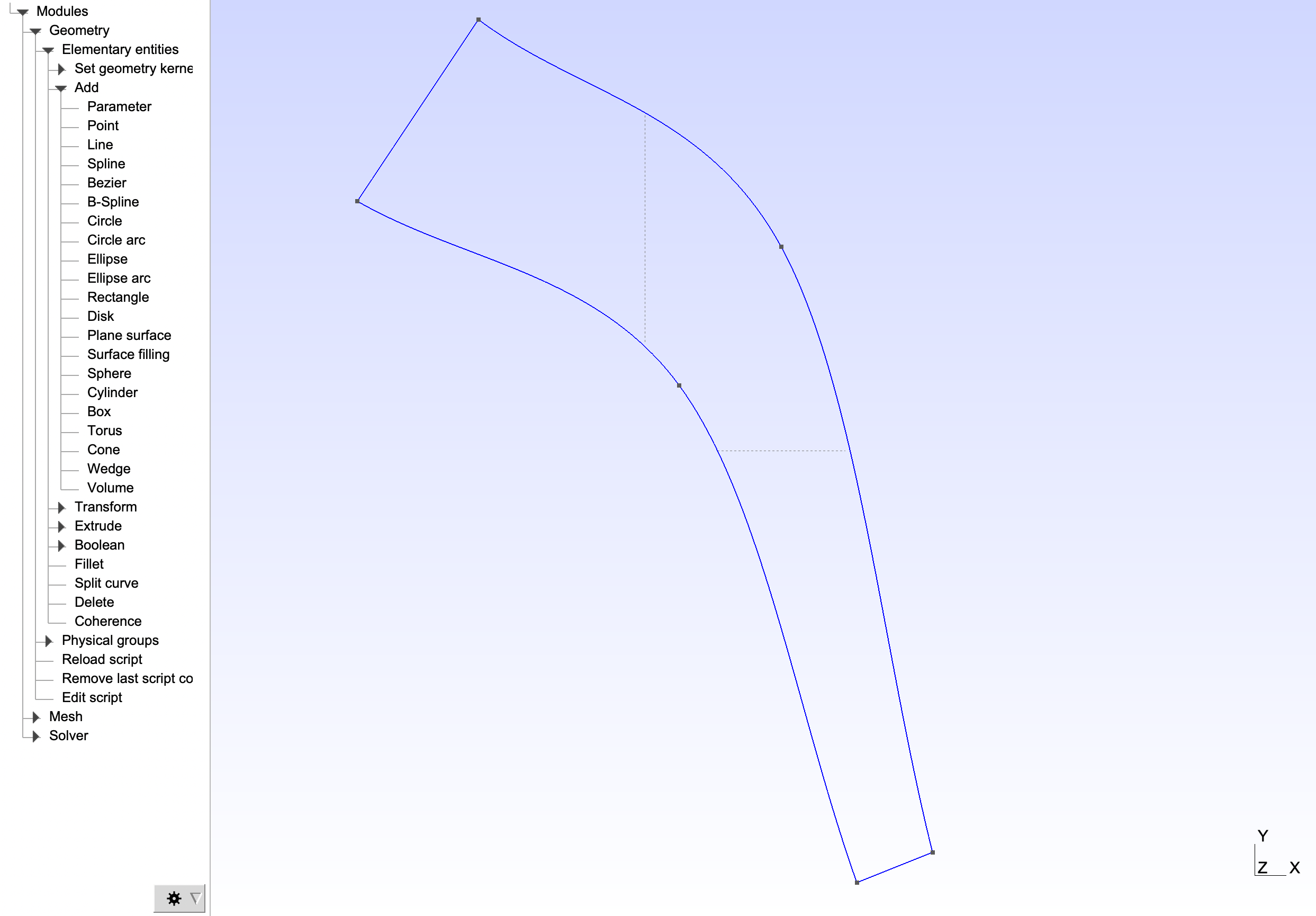
When the splines are created, one has to generate the domain surface. To create this surface, click on Modules > Geometry > Elementary entities > Add > Plane Surface and click on the surface if the splines are in right order. If the splines are not ordered, select each spline one after another. When the surface (or all the splines) is (are) selected, press 'e'.
Gmsh has now created a closed loop and a plane surface. Here is the final geometry :
lc = 600; lc2 = lc/2; lc3 = lc2/2.5;
//+ Points
Point(1) = {-112000, -755000, 0, lc};
Point(2) = {-92000.0, -770000, 0, lc2};
Point(3) = {-82000.0, -810000, 0, lc3};
Point(4) = {-87000.0, -812000, 0, lc3};
Point(5) = {-98724.3, -779176, 0, lc2};
Point(6) = {-120000, -767000, 0, lc};
//+ Splines
Spline(1) = {1, 2, 3};
Spline(2) = {3, 4};
Spline(3) = {4, 5, 6};
Spline(4) = {6, 1};
Curve Loop(1) = {1, 2, 3, 4};
Plane Surface(1) = {1};
Warning
Make sure the edges and the curved loop are correctly oriented. The nodes should be ordered. The script provides an orientation example.
Boundary Conditions
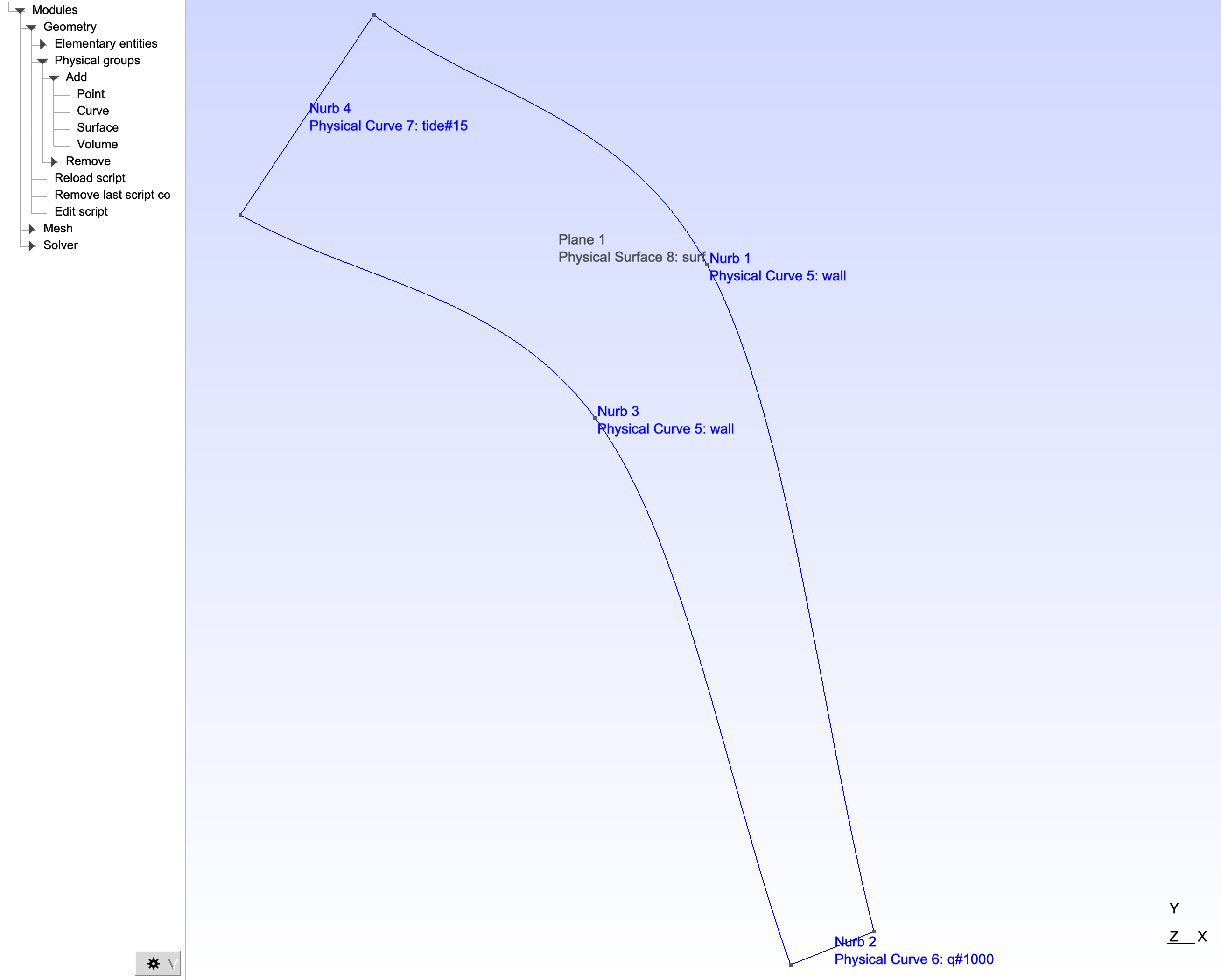
For Tolosa to be able to recognize boundary conditions, one has to declare the domain's boundary conditions in the .geo Gmsh file. Boundary conditions are called Physical Groups. To declare them in our case, one has to click on Modules > Geometry > Physical Groups > Add > Curve. One has to declare the following three boundary conditions (Press 'e' to validate each declaration) :
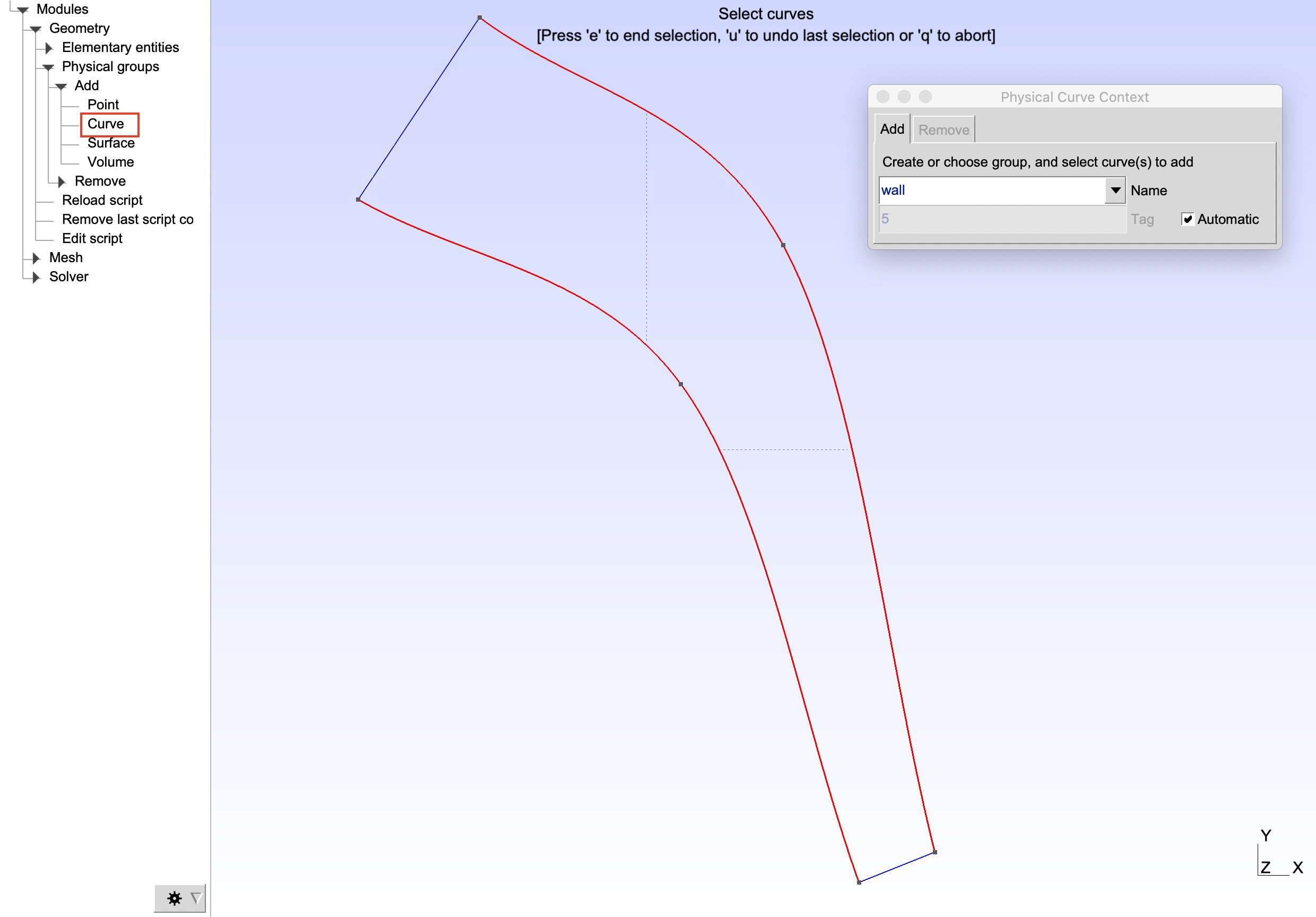
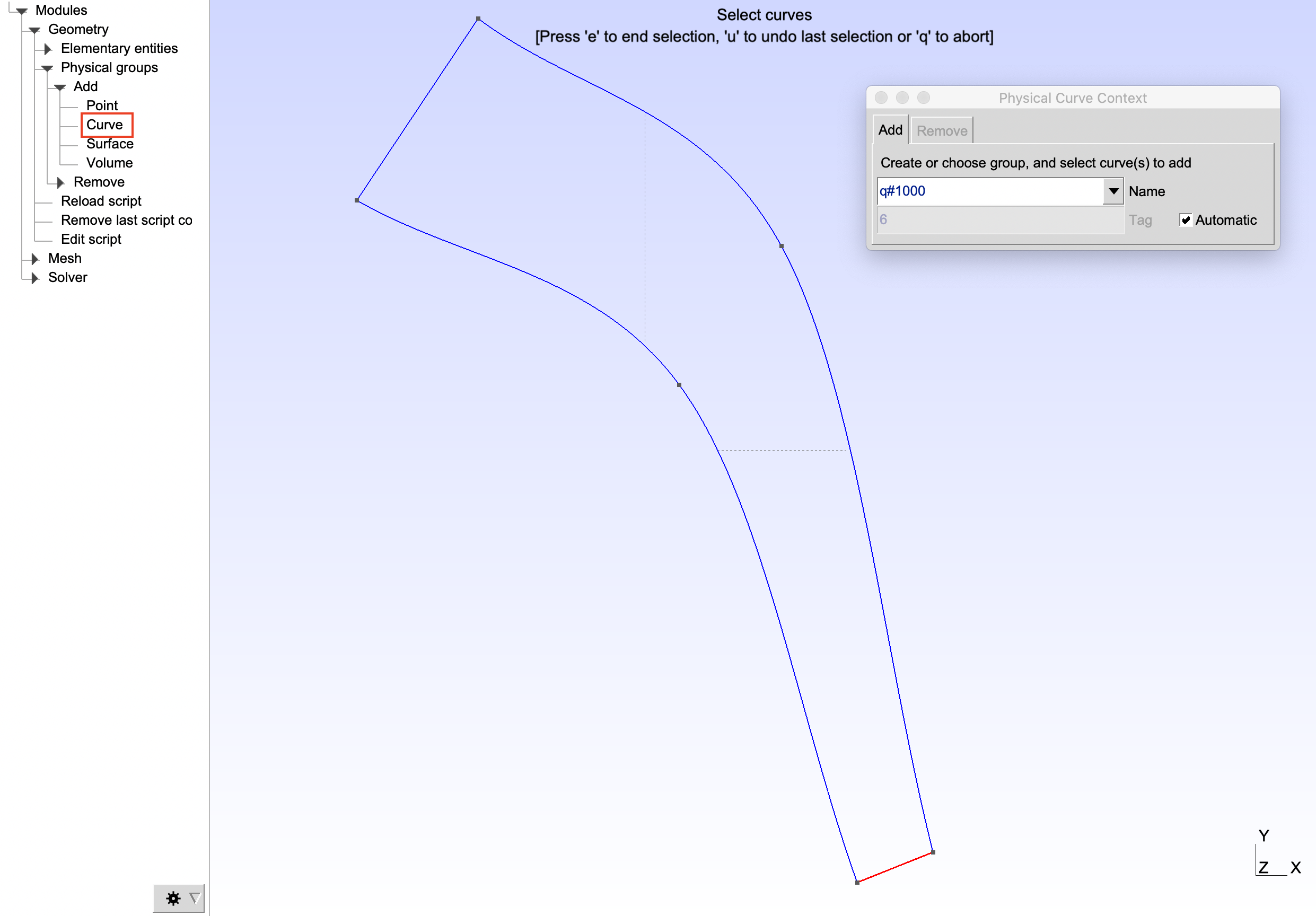
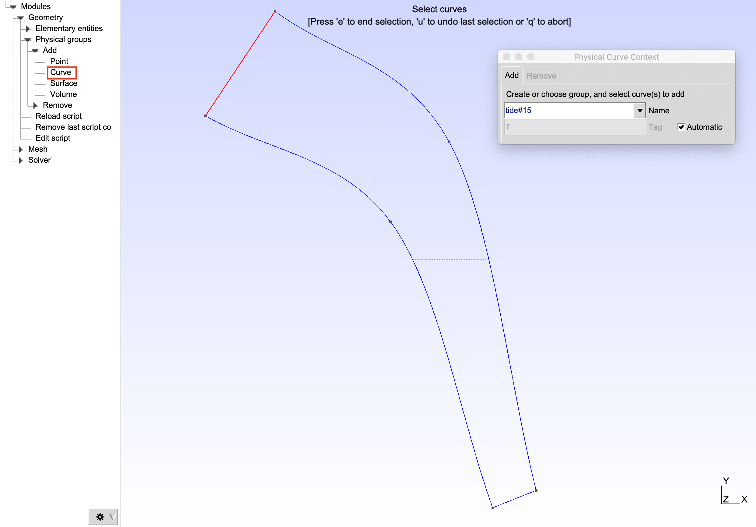
Info
See Ax.: Boundary Conditions to get the boundary conditions syntax and the different methodologies.
When all the edges boundary conditions, one has to declare a surface physical group. Click on Modules > Geometry > Physical Groups > Add > Surface :
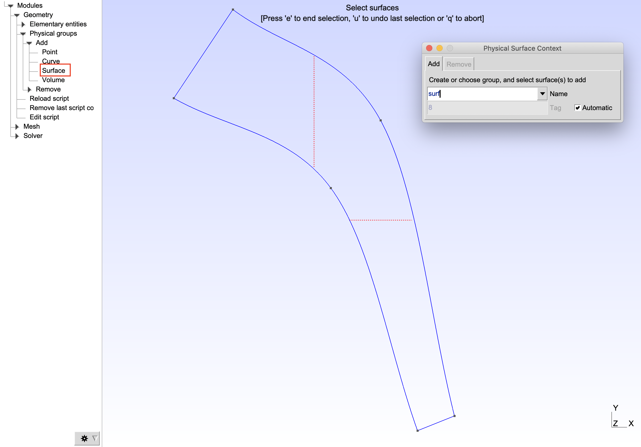
Press 'e' to validate the surface physical group.
The final geometry should now be :
lc = 600; lc2 = lc/2; lc3 = lc2/2.5;
//+ Points
Point(1) = {-112000, -755000, 0, lc};
Point(2) = {-92000.0, -770000, 0, lc2};
Point(3) = {-82000.0, -810000, 0, lc3};
Point(4) = {-87000.0, -812000, 0, lc3};
Point(5) = {-98724.3, -779176, 0, lc2};
Point(6) = {-120000, -767000, 0, lc};
//+ Splines
Spline(1) = {1, 2, 3};
Spline(2) = {3, 4};
Spline(3) = {4, 5, 6};
Spline(4) = {6, 1};
Curve Loop(1) = {1, 2, 3, 4};
Plane Surface(1) = {1};
//+ Physical groups
Physical Curve("wall", 5) = {1, 3};
Physical Curve("q#1000", 6) = {2};
Physical Curve("tide#15", 7) = {4};
Physical Surface("surf", 8) = {1};
When the geometry is created, save it by naming it basic_gir_stereo.geo. Then, close Gmsh.
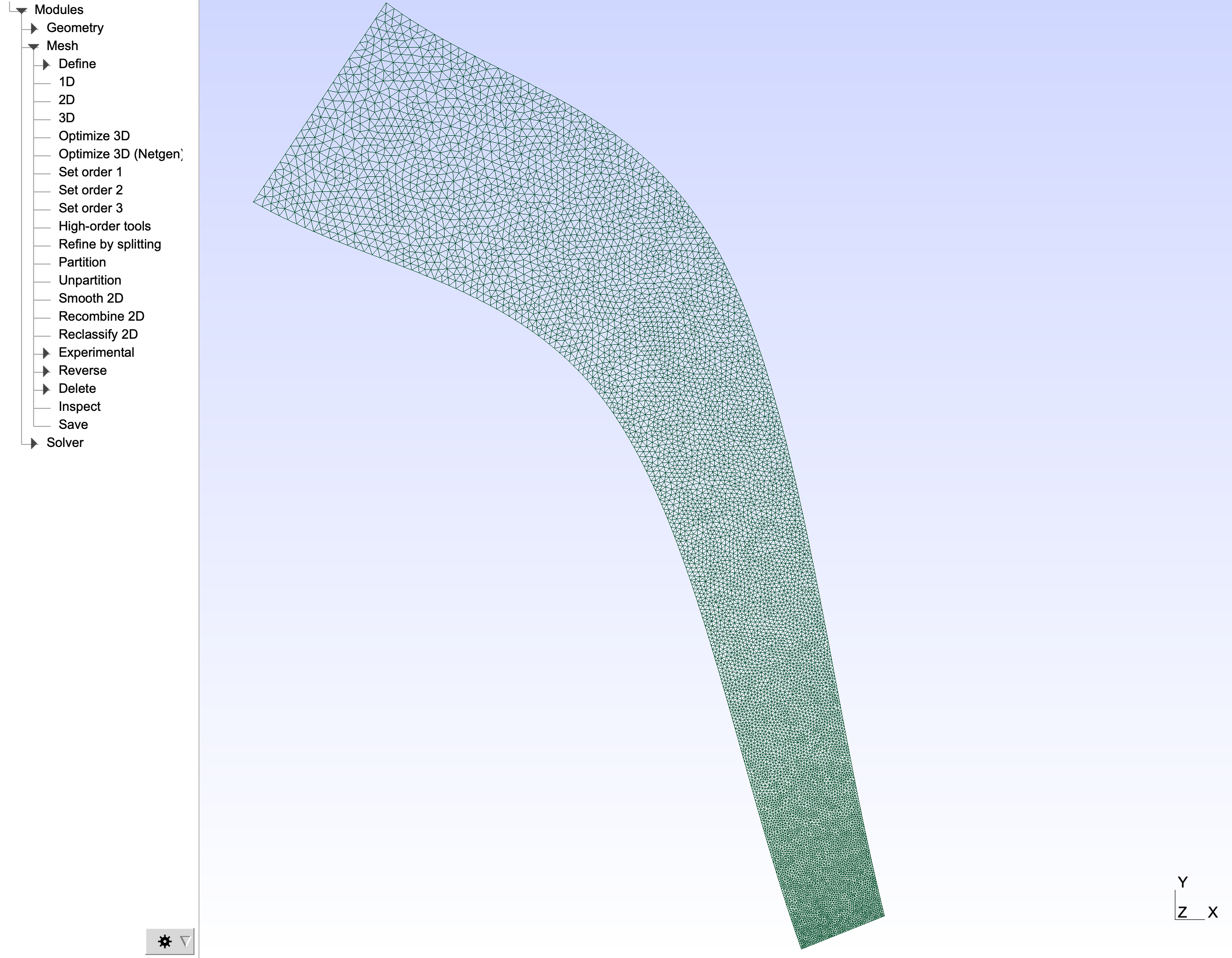
Create mesh
To create the mesh associated with the previously created geometry, write the following command line :
gmsh -2 -format msh2 -algo meshadapt basic_gir_stereo.geo
A basic_gir_stereo.msh mesh file should have been created. The mesh should look like :